
Search
The Renewable Energy site for Do-It-Yourselfers
Large Drainback
System for 16 Unit Apartment
This is a large drainback system to
provide domestic hot water for a 16 unit apartment building in the Pennsylvania.
The system was designed and built by
Alan Rushforth of RushforthSolar LLC -- here is his description of the system:
"Attached are some photos
(before and after) of a solar DHW system I recently finished. It is on a roof
of a 16 unit apartment building. It is a drain back system.
Prior to the installation,
the building was using $4,600 annually in natural gas solely for domestic hot
water. A new 95% efficient Polaris gas water heater was installed along with
this solar DHW system. Not counting my labor, or the gas heater installation,
the project cost $13,645.
Between the new heater and the SDHW system, gas
bills will hopefully be cut by 2/3. I believe a lot of commercial SDHW
applications can make more financial sense than residential applications with
the increased economies of scale. I have adopted commercial solar DHW as a
hobby, and would be happy to help anyone with questions. "
Really a nice job -- thanks very much
to Alan for providing all the pictures and detailed captions!
The pictures show most of the
construction detail.
If you have
questions, Alan can be emailed at: alanrushforth AT comcast.net
(change the AT to @)
Overview:

There are 3 rows of 3 Sunflower
evacuated tube collectors from Fitch Consulting
www.wearesolar.com.
(6 x 30 tube collectors and 3 x 20
tube collectors)
Collector Installation and Supports:

Here is the framework in process. The
steel pyramid bases are 1/8" steel plate. Some cuts and the bends were done a
Fazzio's (a great metal yard in South Jersey). I did the angle cuts and welding.
They were screwed down into wood roof joists and then roofed over with torch
down roofing to make them pretty much zero maintenance. The rest of the frame is
all aluminum with stainless bolts. The horizontal plane of the entire frame is
set on a slight diagonal pitch so when the collectors are mounted, everything
will tilt back to the tank. If the roof were flatter/all one pitch, it might
have been easier and cheaper to mount frames right on the roof, however the
raised framework here allows for easy roof maintenance, and also creates the
nice drainback pitch. The main beams are 3x3x1/8"x 24' long aluminum square
tube. Longitudinal cross members were 2x2x20'x1/8 aluminum square tube. Diagonal
bracing is 1 1/2 x 1 1/2 x 1/8 aluminum angle. The frame came out about the way
I wanted it. Not bouncy. Not overkilled. Galvanized steel would have worked too
and been cheaper, but aluminum should last longer and is easier to work with.

Above is a close up one of the 6
2'x2' x 1/8" steel pyramid bases. The 7/8" threaded rods made adjusting the
pitch easy, although cutting and welding up the bases was a job. Somewhat
lighter gauge steel (like 14 gauge) would have probably been adequate.
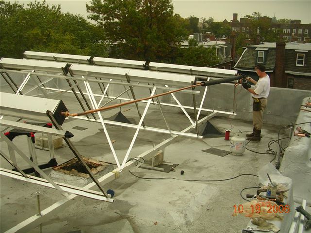
Here we have evacuated tube manifolds installed, and are teeing the arrangement
together with copper piping. Short sections of high temp silicone rubber hose
(from Fitch Consulting) worked well for hose clamping the manifolds together. 1"
thick
armaflex pipe insulation was installed over the piping. Installing the
tubes is the last thing to get done. You don't want to inadvertently create a
stagnation situation with tubes installed before the pumps and controller are
ready to turn on.

To protect the Armaflex from sun and
UV deterioration (this system should last for decades) I wrapped it in foil
faced foam duct insulation from Home Depot. It was not as sturdy and sticky as I
wanted, so I wrapped it again (later photo) with 12' width Peal and Seal roofing
(from
http://www.mfmbp.com/ccp51/cgi-bin/cp-app.cgi ) which is a more durable foil
faced self adhesive roof product.

Above is not wrapped with Peel and Seal yet. The copper pipe runs that span
between the banks of collectors need to be supported so that they do not sag and
create a draining problem. I attached a 2 x2 x 20' aluminum square tube along
the top of each run, to prevent sag. Then covered it all with Peel and Seal.
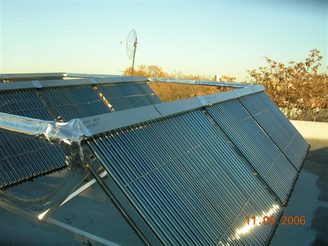
Finished product all wrapped up and
ready for many years of abuse in the elements.
Plumbing and Storage Tank
Installation:

Here is the roof before we started.
The chimney in the middle was no longer used since separate heat pumps were
installed in each apartment and the hot water heater was replaced with a wall
vented 95% Polaris heater. So we were able to take down the top few feet and
convert it to a pipe chase.
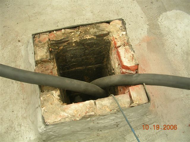
Here are the 1" pex/al/pex lines
covered in 1" armaflex running down the pipe chase (old chimney). Plywood, can
foam, and roofing were sealed up the opening.

Here is the basement before we
started. A bit of a mess.

Here is a 822 gallon STSS tank (http://www.stsscoinc.com
). You can see the folded EPDM liner. Behind it is 2" foam insulation board. The
aluminum skin holds it all together. The tank comes flattened into an oval
shape, in a crate about 4 1/2' high, 11' long, and 18" wide. We uncrated it,
removed the lid on the inside, wrapped the flatted tank in some cardboard and
rope to protect the edges, and dragged it down the cramped basement stairs. Once
down, we tilted it up, opened it into a circle, lifted an edge, and slid the
insulation board bottom circle under, and we had a tank! The orange pipe is 1"
pex/al/pex (which is pretty impressive stuff, probably better than copper in
many ways). We ended up converting the pex/al/pex over to copper before entering
the tank. Special brass compression fittings from
www.Plumbinggoods.com
did the trick. The return line dumps into the top above the water line. We
converted it to copper just outside the tank to put on a ball valve I thought
would be needed to modulate flow. Turns out that valve was not needed. The other
line was the suction line for the pumps that enters the tank above the water
line but dips down to draw water from the bottom of the tank.
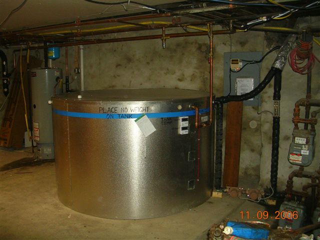
Here is the tank with the insulated
lid on and the plumbing complete. Suspended inside the tank is a 1 1/2" x 120'
copper coil. I used the oversize diameter coil for a bit of tank effect within
the coil - it holds 10 gallons of hot water. When a tenant opens a hot water
faucet, pressurized cold water from the street flows through this submersed coil
on its way to the heater and warms on its way. The water entering the heater is
partially or fully heated by the time it reaches the heater, and the heater come
on much less. On a repeat job, rather than use one large diameter coil, I might
use several smaller coils in parallel that might work equally well and cost
less. The upper black line is the return from the solar collectors. The black
line that runs down to the two pumps on the floor is the copper suction line
that goes from the bottom of the tank up to the collectors. There is a thing
called pump cavitation. As I understand it, under suction within the pump, water
(especially hot water) can vaporize (essentially boil) inside the pump making
noise and shortening pump life. Having adequate pressure in the inlet side of
the pump can eliminate cavitation, as can restricting flow on the exit side of
the pumps. To maximize the inlet pressure in to the pumps, I kept them as low to
the ground as possible. Cavitation was not a problem.
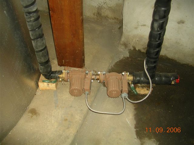
Here are 2 brass Taco 009 pumps.
Brass pumps cost more than iron, but because the tank is vented, and exposed to
oxygen, brass is best because it does not rust.
In this photo you can see the right hand ball valve is throttled half way off to
get the flow from about 10 gpm down where we want it - about 4.5 gpm (.5 gpm per
collector). The Goldline GL30 controller needs return water to be at least 4
degrees hotter than the feed water or it will shut down the pumps. If one left
the flow at 10 gpm, the controller would regularly cycle the pumps on and off.
As a subsequent refinement, rather than throttle the flow down, I hooked up a
delay on timer (for about $30 from
www.Factorymation.com)
that shuts off one pump after a couple minutes (once return flow with siphon
effect is established). With valves wide open, flow then drops from 10 gpm to
4.5 gpm, just where we want it.
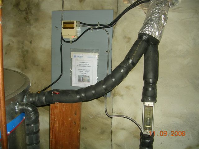
Here you can see the Goldline GL30 on
the wall - pretty simple to wire up. The rectangular metal/glass thing on the
right is a flow meter. There are several makers. The key is get one rated for
higher temps, like 180F, with an appropriate flow scale. I originally had it
mounted lower, but then moved it up centered at the level of the water line in
the tank. That way, when the pumps shut off and the water finishes draining
back, it shows where the tank water line is, which is nice.
LESSONS LEARNED:
RACKS: Racks can be a major labor and
material expense. I was looking for zero maintenance racks, that would not
prevent roof repairs or maintenance. The raised rack design I used achieves that
but was a LOT of work. An added benefit of this rack design was that I was able
to tilt the plane of the racks to facilitate water draining back in to the tank
when the controller turned the pump off. Racks mounted flat on the roof would
save money but would have been less convenient for roofing, and would have posed
separate challenges for how to achieve that critical drain-back tilt.
COLLECTORS:
They were from Fitch Consulting
www.wearesolar.com .
Bill Fitch over there is very knowledgeable and was very helpful with technical
issues. Time will tell how much the gas bill is reduced, but they seem to be
working well. On the first full day of operation, the 822 gallon tank went from
86F to 119F. Since that day was full sun and since the coil was not valved on
yet, it accidentally provided a good test. 6,855 lbs of water was raised 33
degrees equating to about 226,000 btu net deposited into the tank in one day or
just over 28,000 btu/30 tube collector (ignoring piping and tank losses). A word
or caution - evac tube collectors contain a million (seems like it) little parts
to assemble. Allow extra labor. Also the boxing for the glass tubes is pretty
skimpy. Handle carefully and do not stand on end - thin foam end packing does
not cushion the nibs adequately on the end of the glass tubes. 3 tubes out of
240 were cracked at the end, by the time I was installing - but it was not a big
problem. Bill supplied a spare tube with every manifold.
PUMPS:
If one needs to pump water 50' up using circulating pumps that only have a 33'
head, theoretically 2 in series should do the trick. The theory proved correct -
together they do the job. To pump the coolest water from the bottom of the tank
one could cut a fitting into the bottom, or theoretically it could also be drawn
up above the water line from a dip tube. That theory worked also.
PIPE SIZING:
Don't oversize the pipes. For cost purposes, and heat loss purposes, bigger is
not necessarily better. On this size system, if the head were lower, and only
one pump were used, or if one were going to leave both pumps on, 3/4" pipe would
be adequate (instead of the 1" I used). Using the smallest pipe that will do the
job, will help hold down pipe and pipe insulation costs as well as cut surface
area heat loss a little.
COPPER PIPE vs. PEX.:
The common wisdom is you must use copper for lines back and forth from the
collectors to handle high stagnation temps. I felt on a drain back system, where
during stagnation, there is no liquid in the collectors, Pex/al/pex (premium pex
with an aluminum layer inside) should work for all the run except the last
couple feet to the collector, where you might pick up more of that stagnation
heat. It turns out Pex/al/pex is very impressive pipe. The aluminum embedded in
the pex seems to be about 1/32" thick and the pipe is rated for 80 psi at 200F.
So far it is working fine, and I have confidence it will continue to do so.
Note: pex/al/pex has a slightly bigger diameter than regular pex and uses its
own special compression fittings. You do not need to buy a pex crimper to use it
- just the right compression fittings. (I learned that the hard way).
PIPE INSULATION:
1" armaflex (extra thick -special ordered from a HVAC supply) worked well. Peel
and Seal roofing worked well to wrap it and protect it from the elements. To
boost tank insulation, (especially desirable on more oversized tanks) one might
pick up 2) 4x8x 2" foam sheets and lay them down first under the tank before
installation, to double the bottom insulation. One can always wrap the sides and
top later with extra insulation if wanted.
TANK SIZE:
I believe in this type system where the tank is a simple non-pressurized,
relatively low cost item, comprising a small percentage of total system cost
(less than 15%) one can afford to spring for a larger tank that contains more
gallons per person than normally recommended. I used 822 gallons with 51 gallons
per apartment, (typically one person in each of these apartments). Although this
is more storage than the 20 to 30 gallons per person often recommended, it still
did not provide as much 'flywheel effect' as I had hoped. From spot checks,
November tank temps bounced from the mid 70's to the upper 120's. If I were to
do it again, and if the tank would fit, I would increase the tank size to
provide 80 gallons or more per unit which I believe would better absorb heat
from sunny spells, carry it into cloudy spells, improving overall performance.
TANK DETAILS:
When ordering an STSS tank, one specifies how many tank inlet sleeves one wants
installed. In this case it was 4 total, 1 for the collector feed, 1 for the
collector return, 1 for street pressure feed to the coil, and one for the exit
from the coil to the gas heater. Unless you specify otherwise, all 4 will be
mounted all in a row spaced about 6" apart. For optimal piping runs, I needed
one on the opposite side of the tank, so I removed one, moved it, and patched
the hole (all above the water line). If I were to do it again, it would be
better to plan out and specify tank pipe entry locations, or at least order an
extra sleeve fitting or 2 in case field modification are desired.
Alan Rushforth
Rushforth Solar LLC
www.RushforthSolar.com
AR@RushforthSolar.com
Bryn Mawr, PA
Gary 1/2/0


