Search
The Renewable Energy site for Do-It-Yourselfers
Effect of Vent Size on Thermosyphon
Collectors
|
This is a small test to
determine the effect of changing the inlet and exit vent size on the
output of a thermosyphon collector.
Thermosyphon collectors
operate on the chimney effect created inside the collector. Solar
radiation warms the absorber, which transfers heat to the surrounding
air, warming it and making it lighter so that it rises out of the
collector and pulls new air in. This is a relatively weak driving
force compared to fan forced collectors, so the collector must be
designed for low resistance to get enough airflow to operate
efficiently. |
|
The collector used for the test is my
shop heating
collector ....
A lose rule of thumb for sizing the
inlet and outlet vent area of a thermosyphon collector is to use one half the
collector cross sectional area. So, if the collector was 24 inches wide
and 6 inches deep, the cross section would be 6*24 = 144 sq inches, and the rule
of thumb vent area would be 50% of that, or 72 sq inches.
This 50% rule makes for some fairly
large holes in the wall.
The question came up as to how much
of a hit you would take if you reduce the vent area below the 50% rule.
This is a quick test to get an idea
of the performance hit for reducing the area first by one half (25% of cross
section), and them by 3/4 s (12.5% of cross section area).
|
Test of effect of vent size on thermosyphon collector output |
|
|
|
23-Sep-08 |
|
|
|
|
|
|
| |
|
|
|
|
|
|
|
Time |
Vent |
Velocity (fpm) |
Delta T (F) |
Vent area (sqin) |
V*dT*A |
Performance (%) |
|
11:52 AM |
full open |
130 |
29 |
72 |
271440 |
100.0% |
| |
|
|
|
|
|
|
|
12:04 PM |
half closed |
158 |
34 |
36 |
193392 |
71.2% |
| |
|
|
|
|
|
|
|
12:14 |
3/4 closed |
180 |
51 |
18 |
165240 |
60.9% |
| |
|
|
|
|
|
|
The vent area for the "full open"
condition is 72 sq inches, and this is equal to 50% of the cross sectional area.
The "half closed" condition cuts this
in half to 36 sq inches.
And, the "3/4 closed" condition
(surprise) cuts this by 3/4's to 18 sq inches.
On the half closed and 3/4 closed,
both the top and bottom vents were blocked by these amounts.
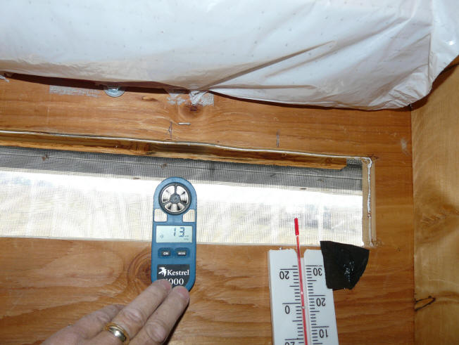
The velocity is measured in the
middle of the top vent opening with a Kestrel wind meter in feet per minute.
The temperature at the inlet and
outlet vents is measured with some hardware store alcohol thermometers.
The plastic around the bulbs was cut away so that they would not restrict
airflow.
The V*dT* A column is the product of
the (vent velocity)(Temperature rise through collector)(Area of vent) --
this product is proportional to the collector heat output. The actual heat
output would be (V)(A)(density)(dT)(Cp) Where V*A*density gives the weight
flow, and Cp is the specific heat of air.
In each case, the data shown is an
average of 3 to 5 readings taken at about 2 minute intervals. There was
very little variation from reading to reading for the same vent setup.
The collector was given about 4
minutes to stabilize after each vent change.
The Performance column shows the
comparison of the heat output of the baseline (full open) collector to the half
blocked and 3/4 blocked conditions.
The significant fall in thermal
output of the collector leads me to believe that you can't get away with vents
that are too small. It would have been nice to start with vents that are
the same size as the cross section, and then go down to 75%, 50%, 25% ... to see
what the effect was all the way down, but I did not feel like cutting larger
holes in my wall to get to 100%. The test clearly indicates
that not nearly all of the air resistance is in the absorber -- the vent size
and presumably the vent and cross section design have significant air resistance
and changes to these to reduce air resistance might yield performance
improvements. Working on an optimal cross section and vent design would
seem like a good project for someone -- maybe you?
Comments welcome...

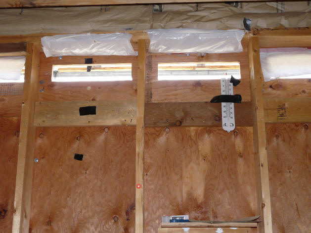
upper collector vents -- this is the baseline, no blockage, 50% of cross section
vent.

Measuring wind velocity and
temperature.

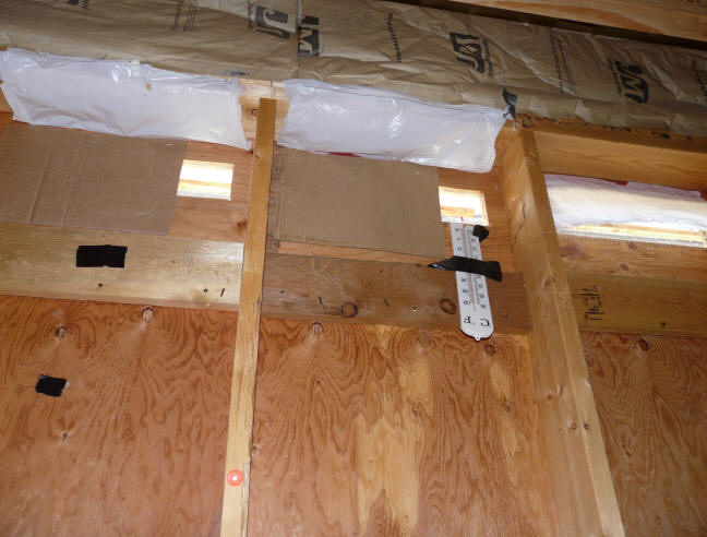
Vents are 3/4 blocked with cardboard
stapled over the vent openings.
Both the top and bottom vents were
blocked the same amount.
Gary September 23, 2008, December 6,
2008
